|
Chapter 32 : Light Reflection and Refraction |
32.1 : The Ray Model of Light | |
|
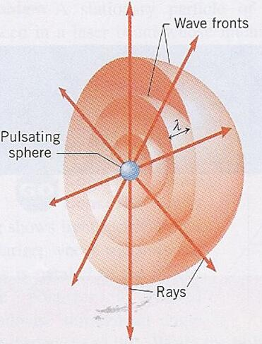
Consider our little spherical carbon nanotube speaker, putting out sound uniformly in all directions. These sound waves spread out from the speaker. We can take a point on each wave (where the pressure is equal to it's maximum value, for example) and call that a wave front. These waves are spreading spherically from the source so each sphere (each wave front) is perpendicular to the radius vector from the source We'll call that vector perpendicular to the wave front a ray.
|
|
|
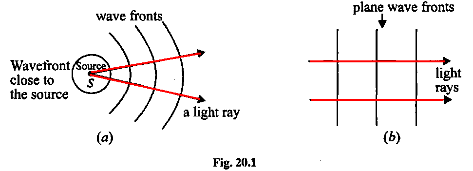
The figure below is a cross section through the figure above to more clearly showing the rays and wave fronts that describe how the sound is spreading out from the speaker.
Note that if we're `far enough' away from the source, the nominally spherical wave fronts become more parallel, turning into what are called plane waves. | |
| |
|
We can analyze waves in two ways then: looking at the waves themselves (via the wave equation), or following the rays since we know the wave fronts will be perpendicular to those rays. Both approaches (models) have their uses. Light can also be analyzed both ways.
We'll start with the ray approach, which is called Geometric Optics. | |
|
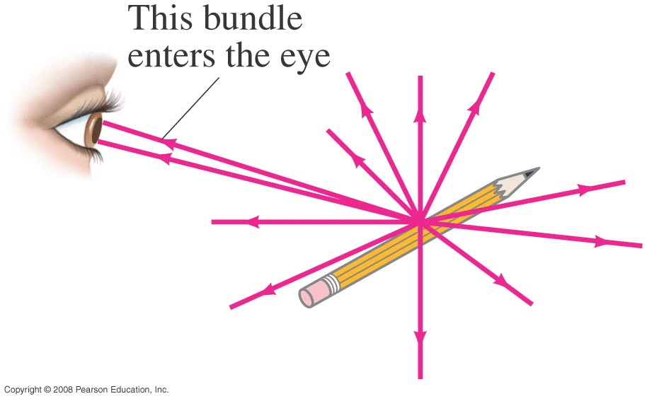
How do we 'see' on object?
Focusing on the 'ray' model, ambient light in the room hits the object and is scattered in 'all' directions, with some (tiny) small fraction of those photons making it through our pupil to our retina. |
![]() |
|
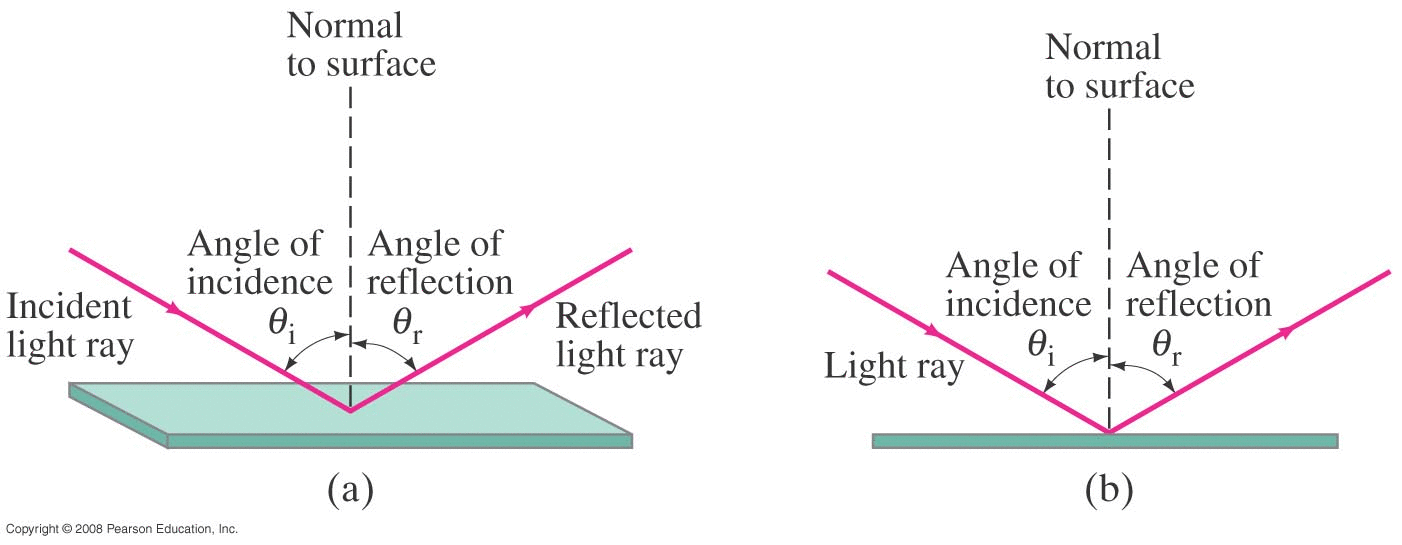
What happens when a photon 'bounces off' a surface? The figure is annotated with some terms we'll use to describe this effect. In particular note that the angle of incidence and angle of reflection are measured relative to a line that's normal (perpendicular) to the surface at the point where the photon strikes the surface.
|
|
|
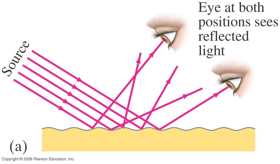
Most materials aren't perfectly smooth or even perfectly reflective, and incoming rays get scattered in other directions. This is called diffuse reflection. (Each photon still follows θr=θi but the angle of the surface itself isn't constant.) |
|
|
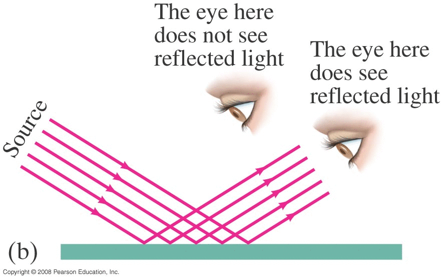
The smoother and more reflective a surface is though, the less the scattering is, ultimately yielding specular reflection. |
|
Example: Corner Reflector |
|
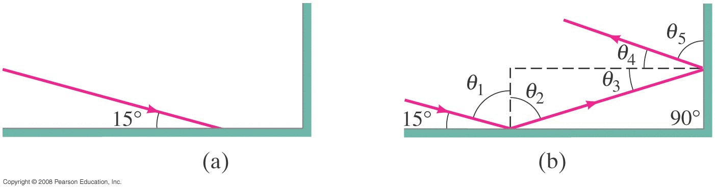
Suppose we have two mirrors at right angles. What happens to an incoming ray of light (photon)?
|
Example: Real Corner Reflector | |
|
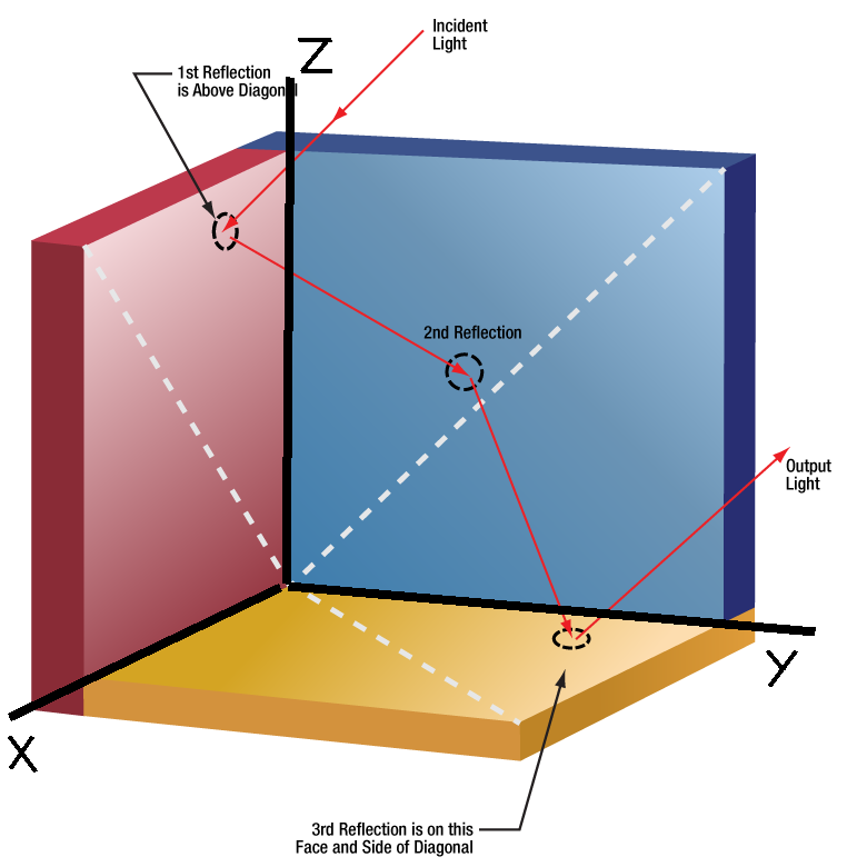
Let's extend this to a full 3-D corner reflector. Note from the previous figure than when the ray (i.e. the photon) hit the mirror aligned with the X axis, it's vx didn't change but it's vy (the component of velocity perpendicular to the surface) flipped its sign. Consider the vector velocity v of the photon.
Net result: the outgoing velocity vector is in exactly the opposite direction as the incoming velocity vector.
|
|
Example: Lunar Range Experiment | |
|
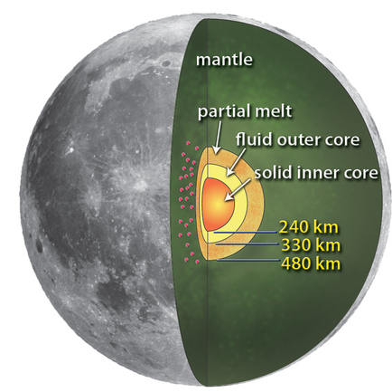
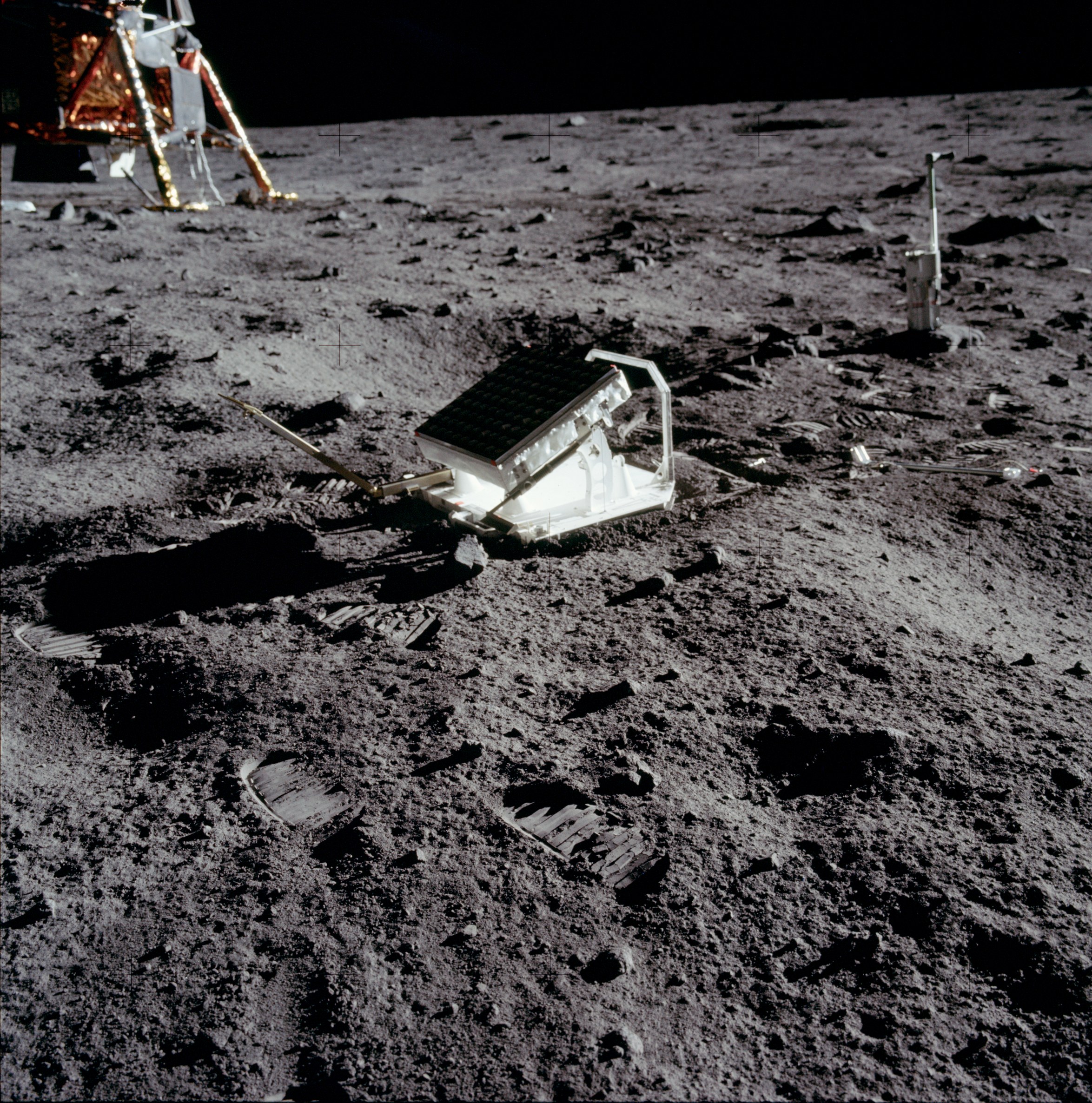
Several of these retro-reflectors have been placed on the moon, starting with the original Apollo 11 mission in July 1969. Apparently 7 are still operational, including that first one, and including one deployed recently (March 2025) during a commercial robotic landing. By measuring the travel time from the Earth to the Moon and back, the distance to the Moon can be measured to within a few millimeters now. List of retroreflectors on the Moon (Wikipedia) Among other things, these reflectors have shown that:
|
|
|
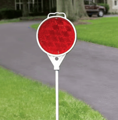
Driveway Corner Reflector
|
Apollo 11 Lunar Laser Ranging Experiment
|
Image Formation with a Flat Mirror | |
|
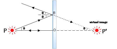
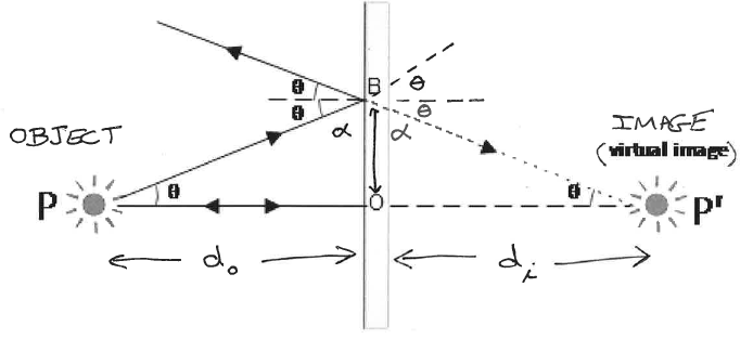
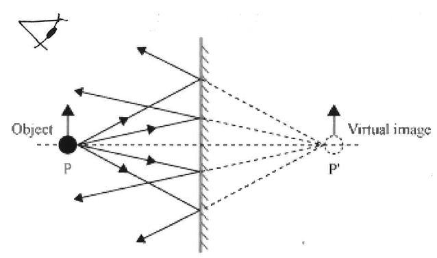
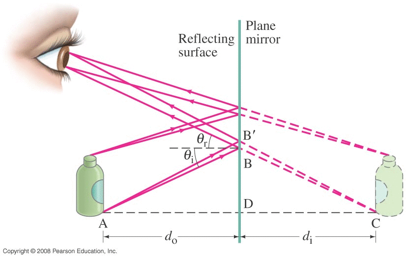
Let's look at light rays (photons) from a point source (or a single point on some 3D object) and see how they reflect from a flat mirror, ultimately creating an image that appears to be behind the mirror. |
|
![]() |
![]() |
![]() |
![]() |
32.3 Formation of Images by Spherical Mirrors | |
|
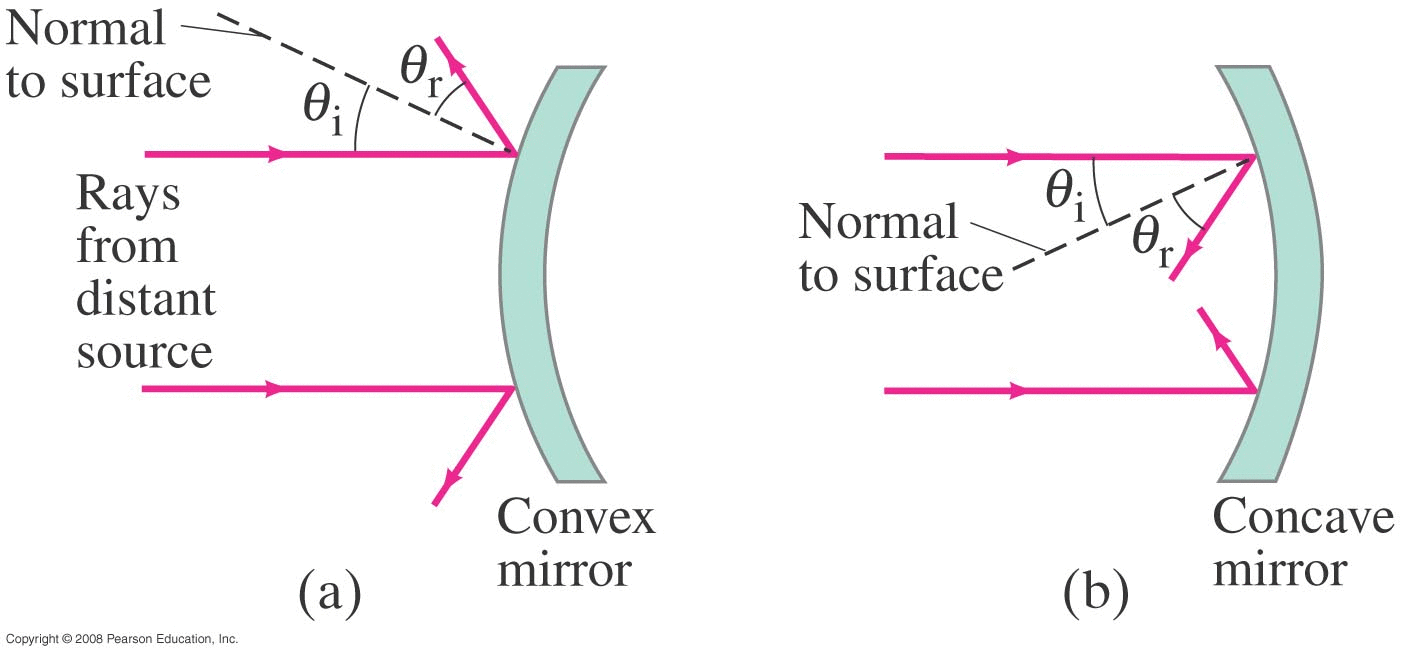
Consider the two types of spherical mirrors. Left figure below: the mirror 'bulges out' towards us and is called a convex mirror Right figure below: the center of the mirror is farther from us, like we're looking into a cave, and this is called a concave mirror. Note in each case θr=θi. |
|
|
|
|
|
NOTE: • If the object is far away a CONVEX mirror will create an image that appears to be behind the mirror and is called a VIRTUAL image. An image sensor (or piece of film) placed there won't record anything since the photons never actually reach that point: they just appear to be coming from there. • Similarly, if an object is far away a CONCAVE mirror will create an image that is in front of the mirror. We can put a sensor there and actually record something since the photons really do pass through that point. This is called a REAL image. (Example: telescope mirrors.) |
|
How much do we have to worry about the curvature of the mirror? | |
|
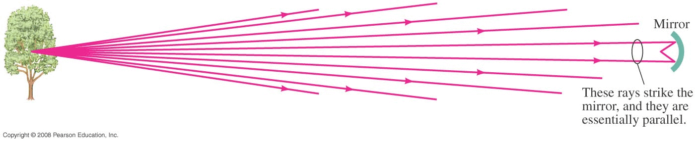
First, if we're looking at something far away, what do the rays themselves look like:
They're essentially parallel as long as do >> R |
|
|
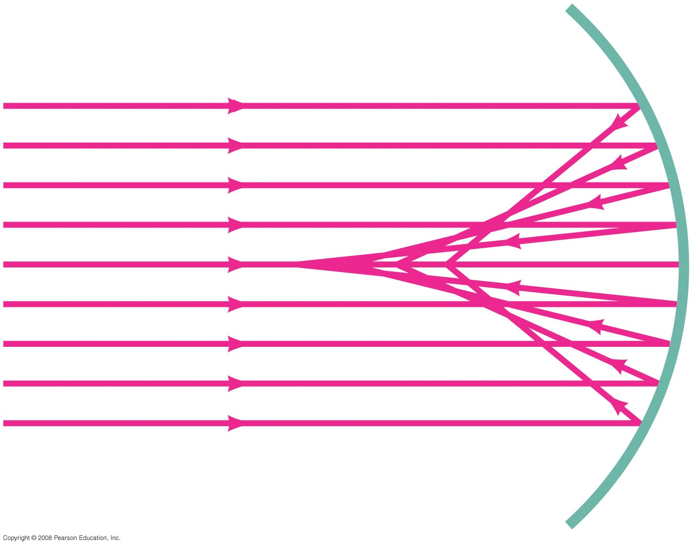
OK, what will these parallel rays do when they hit the mirror?
That looks bad, but in actual telescopes the radius of curvature of the mirror is very large compared to the actual size of the mirror. These mirrors look almost flat to the naked eye.
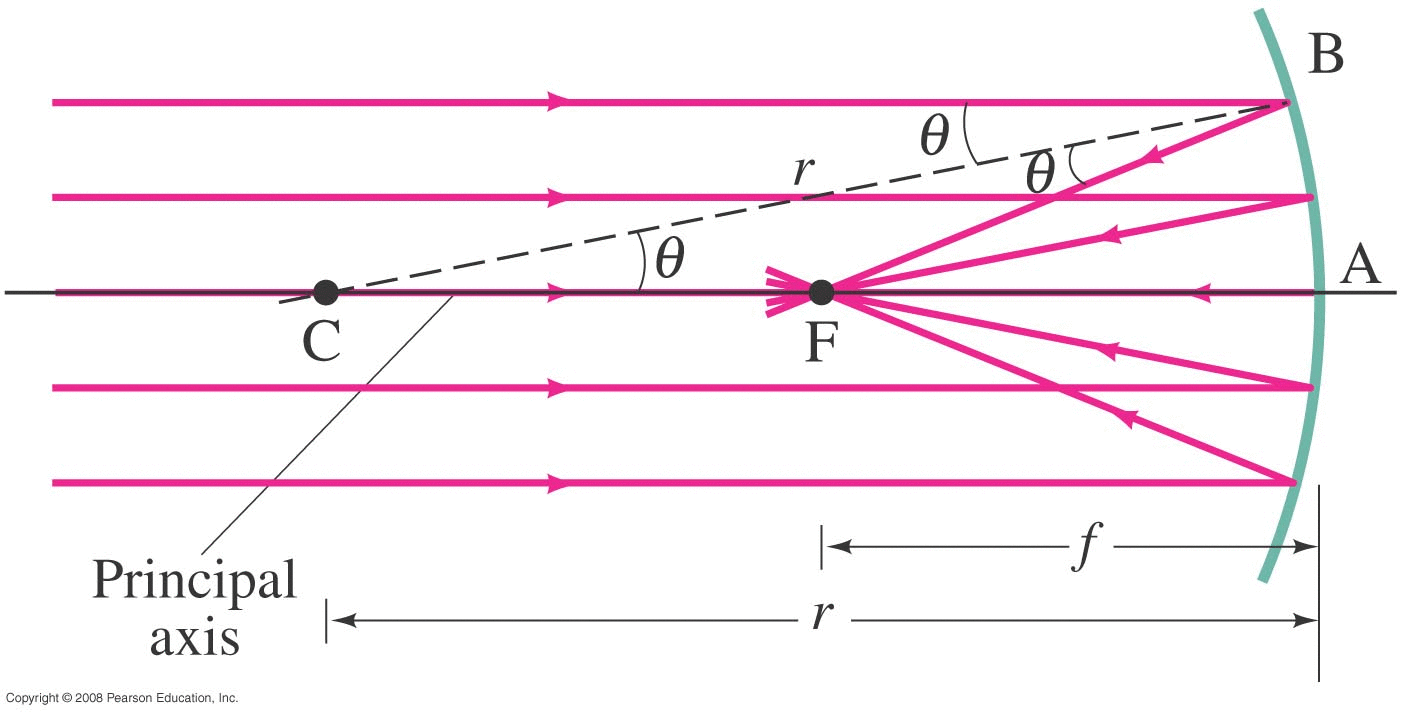
Let's derive the location where each photon hits the principal axis (the line from C to the vertex of the mirror). |
|
|
| |
|
Follow the ray at the top of the figure. It's located a distance y from the principal axis. That photon hits the mirror at point B, reflecting as shown. (the dotted line is a radius, running from C to B, so that dotted line is perpendicular to the mirror at point B) The photon (ray) then passes through the principal axis (somewhere) at point F. (Point F will be called the FOCAL POINT of the mirror. We'll see why.) This creates an isosceles triangle CBF. It's isosceles, so CF is the same length as BF, which we'll call x. We want to determine how X depends on Y. Drop a perpendicular from F to the dashed line (of length r), cutting it into two segments, each of length (r/2). Trig: cos(θ) = (r/2) / x Trig: sin(θ) = y/r Combine using cos2θ+sin2θ=1 and find: \[ x = (\frac{r}{2})\frac{1}{ \sqrt{ 1 - (y/r)^2 } } \] We made no approximations here, so this is the exact location for a spherical mirror. In actual telescope mirrors y/r will be extremely small, so x will be very nearly (r/2). How 'nearly' and what impact does this have? | |
|
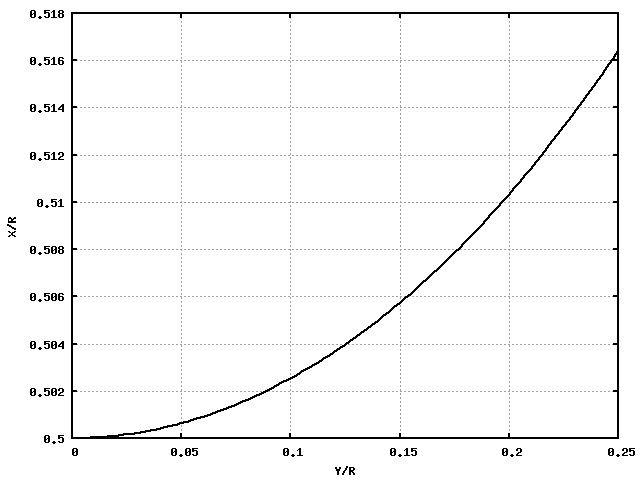
Moving an r from the right to the left, we can write that equation as: \[ \frac{x}{r} = \frac{ 0.5 }{ \sqrt{ 1 - (y/r)^2 } } \] y can never be larger than r, and is usually much smaller, so here is a plot with (y/r) varying from 0 to 0.25 |
![]() |
|
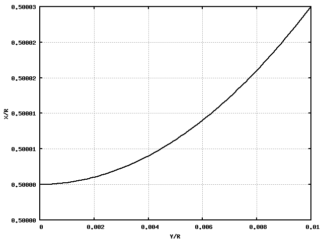
Here's a similar diagram for the Hubble telescope's main mirror, which has a diameter of 2.4 m and a radius of curvature of r=115.2 m. The largest that (y/r) can be now is (1.2/115.2) or about 0.01. Here's a plot using that 'worst case' as our limit. Rays near the principal axis will hit at x=57.6000...m. The worst case rays will hit at x=57.603..m or just 3 millimeters away. If we put a detector or piece of film at x=r/2, light rays coming from a point on some distant object (say Mars) don't all focus at the same point exactly, resulting in a (minute) level of blur. We can fix that though! |
![]() |
A Shape with an Exact Focal Point | |
|
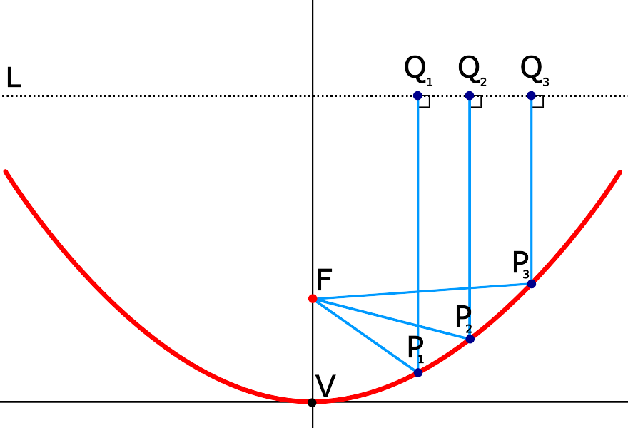
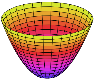
There is a geometric shape for which all parallel rays actually do intersect at exactly the same point: a paraboloid. Start with a parabola and rotate it about its central axis: \[ y = \frac{1}{4f} x^2 \] where f is the distance from the vertex to the focal point F of the parabola. |
|
![]() |
![]() |
|
How not-flat is the Hubble mirror? Let y be the depth of the mirror and x be its radius (actual physical size; not the radius of curvature). For Hubble, R=1.2 m and F=57.6 m which yields a depth of just 0.63 cm! To the naked eye, the mirror would appear almost flat. | |
Parabolic Reflectors : Examples | |
|
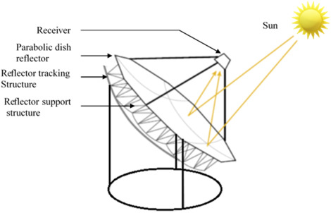
Solar Collector
|
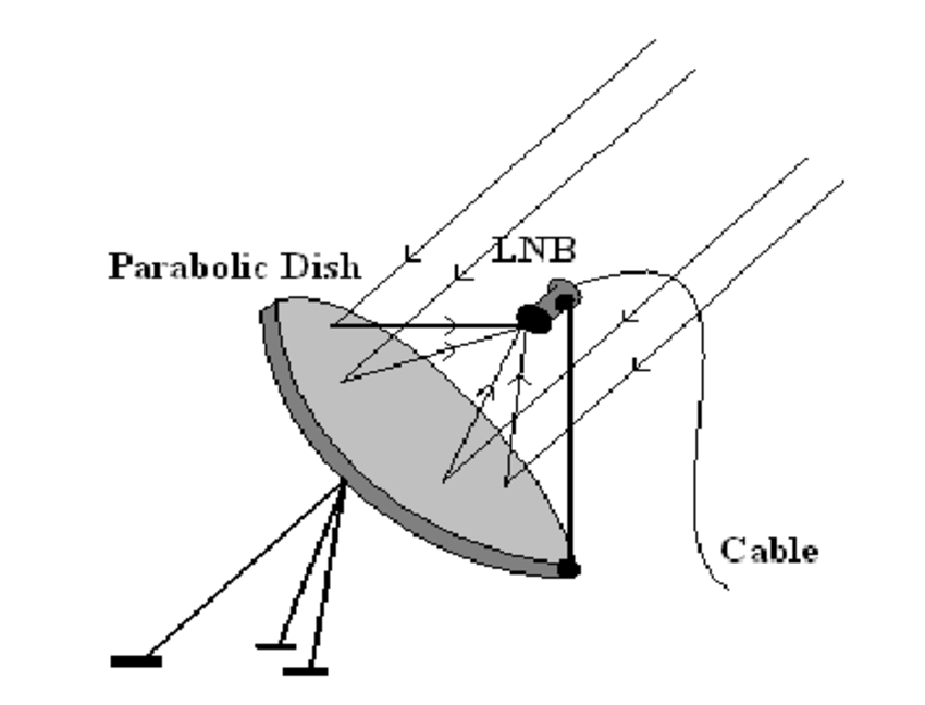
Satellite TV
|
|
Satellite TV (why is antenna not centered?)
|
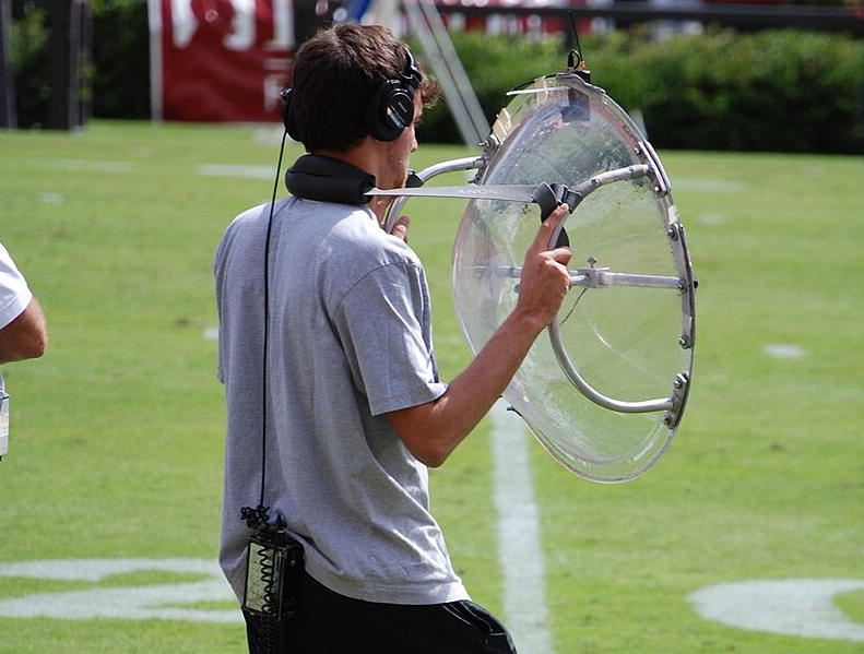
Audio Example
|
|
Radio Telescope
Mounts allow 'aiming' at specific objects in sky |
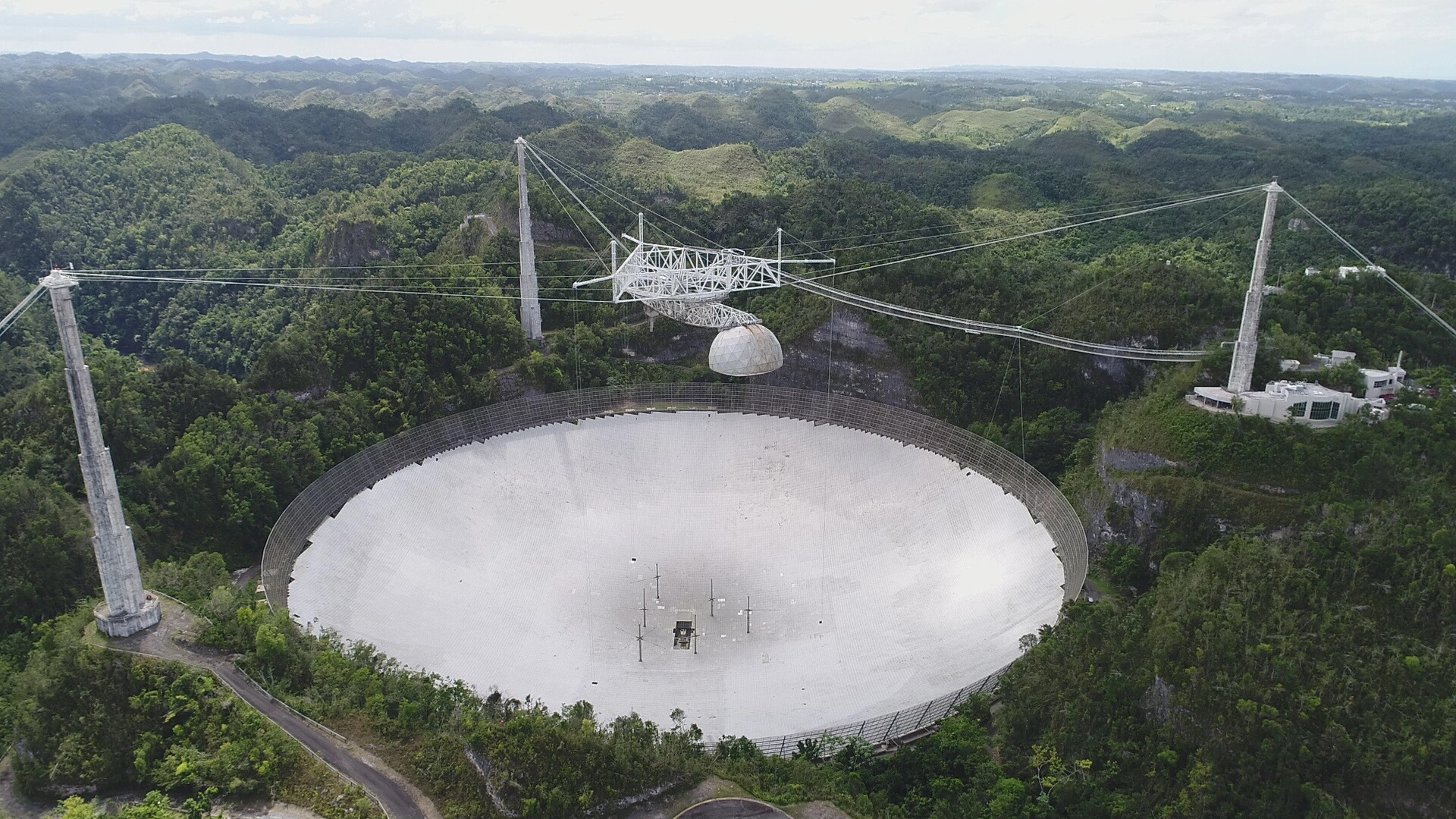
Radio Telescope (former)
Arecibo radio telescope (destroyed in Dec 2020 when cables snapped) |
| Addendum: Additional 'Corner Reflector' Examples |
|
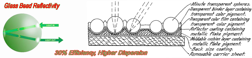
Glass Bead reflector
|
|
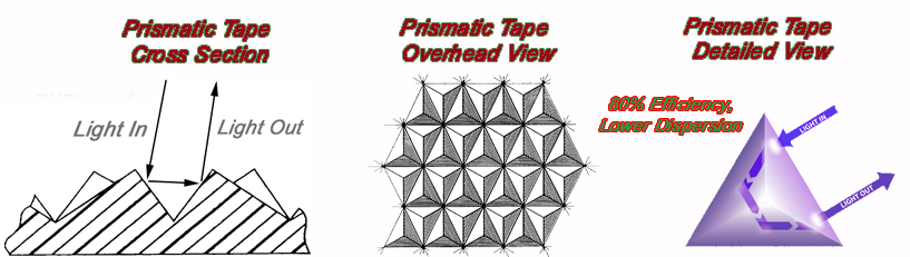
Prismatic Reflector
|